Oi Look Here and Read This. Draw the following lines used in projection.
Leader Lines Toolnotes
170 mm 235 mm Binding.

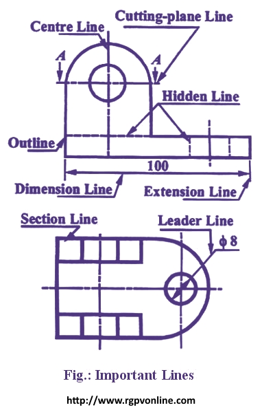
. Visible lines are drawn as solid thick lines. A leader is a thin line used to connect a dimension with a particular area figure 24. Various types of lines as used in drawing of an object are shown in Figure and discussed below.
Continuous thin line find its application in engineering drawing as Dimension line Projection line Leader line. More specifically the arrow size arrow inclination the text size allow line weight etc should all be the same for all leaders in. Technical drawing Lines are used for different purposes to provide specific information for designers manufacturers etc.
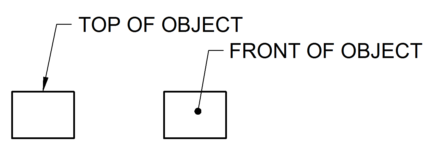
It is used by. A Dimension is a numerical value expressed in appropriate units of measurement and used to define the size location orientation form or other geometric characteristics of a part. This can be a dot if the line ends within the outline of the part an arrow if the line touches the outline or centre line of a feature or without either an arrowhead or a dot if the line touches a dimension.
Technical Drawing Line Types. A drawing leader consists of an arrow and a text. Two or more adjacent leaders on a drawing should be drawn parallel to each other.
All dimension lines terminate with an. If possible dimension lines are aligned and grouped for uniform appearance. ENGINEERING DRAWING PLANE AND SOLID GE O M ETRY By N.
Leader line is the thin solid line used to indicate the feature with which a dimension note or symbol is associated. 7 Thin chain line find its application as. Detail- On the end opposite the arrow the leader line will have a short horizontal shoulder 3 mm long.
Leaders should have a uniform and consistent appearance at all drawings independently of the drawing scale. A type Continuos Thick. Whats New in SOLIDWORKS Electrical 2020 - Leader Lines.
Plus and minus dimensioning is the allowable positive and negative variance from the dimension specified. Leader lines - Engineering Drawing notes in drawing. Continuous thin wavy Irregular boundary lines short 2H.
C type Continuous THIN Freehand. Paperback with Four color Jacket Cover Pages. You can create leader lines with blocks and notes in 2D panel layouts and harness drawings.
Linetypes And Weight Standards In Technical Drawing. On mechanical engineering drawings. This line is used to display the outline and edges of the main drawing done with a pencil softer than HB.
In general application thick lines are 06 mm 024. A hidden line also known as a hidden object line is a medium weight line made of short dashes about 18 long with 116gaps to show edges surfaces and corners which cannot be seen. Lets see what types of lines used in engineering drawings.
The expression of details in terms of numerical. Exercise Complete three orthographic views of the object shown on the next slide. The continuous thin line is the most frequently used line type on Engineering Drawings.
Line types are also a language type to communicate between technical people. 2015 Reprint ISBN. Leader Hatching type lines must be drawn thin and continuous.
These lines are solid and has no break in them. Leader lines and Termination of the dimension line. Leader lines should be inclined between 15 o to 75 o.
An Engineering drawing should contain the details regarding the sizes besides giving the shape of an object. Imaginary lines of intersection. The lines are defined as follows.
What are the types of line in drawing. For More Engineering Drawing MCQ Click Here. The person who will read drawings have to learn what they mean.
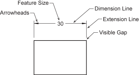
Looking at the drawing. B Dimension lines show the direction and extent of dimension. Dimension lines are used to show the extent and the direction of dimensions.
Visible lines represent features that can be seen in the current view. Continuous thin Dimension lines leader lines extension lines Construction lines 2H Hatching lines. A leader may also be used to.
In other words indicating on a drawing the sizes of the object and the other details essential for its construction and function using lines numerals symbols notes etc is called dimensioning. But 30 o to 60 o is preferred. Engineering Drawing An engineering drawing is a precise technical graphic model that communicates design intent.
Line conventions in engineering drawing. B type Continuous THIN. The leader line itself should be a continuous Thin line see this post on Linetype Definitions.
A leader points to a bit of our drawing and says. A slash or a dot in architecture. Extension lines begin 15 mm from the object and extend 3 mm from the last dimension line.
A leader line also has a terminator. I Extension line ii Leader line iii Construction line नमनलखत लइन क खच - Answer. A leader line consists of two parts.
Examples of leader lines with arrowheads and dots are shown in the vice assembly and the movable jaw drawings. Continuous thin line find its application in engineering drawing as Dimension line Projection line Leader line. Here is the list of cases where the continuous thin line will be used.
For general engineering drawings the types of lines recommended by the Bureau of Indian Standards shown in table 2 must be used. Often they are omitted in an isometric view. A harder pencil should be used such as a.
In drawings that do not have cutting planes visible lines will be the thickest lines drawn. Thick and visible line. Thin lines are nearly 03 mm 012 in most technical drawings.
A leader line is a line that establishes a connection between a graphical representation of an item and some text. All of the above. C Leader lines are used to direct an expression in note form to the intended place on the drawing.
Text is extended from this shoulder such that the text height is centered with the shoulder line. In SolidWorks inserted dimensions in the drawing are. To create a leader line on the Draw tab under Annotation click Block leader or Text leader.
720 16 33000 About the book CoNteNt The book provides all aspects and detailed study of Engineering Drawing Plane and 1. Related Questions on Engineering Drawing. Sometimes they are used to make a drawing easier to understand.
A leader line is a thin line on a design or blueprint that is used to connect a dimension line with a particular area or point on the drawing. Avoid chain dimensioning especially for mechanical objects. 7 Thin chain line find its application as.
A Extension lines are used to indicate the extension of an edge or point to a location outside the part outline. Leader line Dash thick line Hidden line Chain thin line Center line. Tolerance is the amount a particular dimension is allowed to vary.
The thickness of the lines must be chosen according to the type and size of the drawing from any of the six groups given in Table 1. Following are the different types of lines used in engineering drawing. These lines are used for the main lengths of the object view.
Figure 24 - Example drawing with a leader. This line is basically used for dimension extension projection leader line etc. Thin hidden lines are used as intermittent line types.
Draw The Following Lines Used In Projection I Extension Line Ii Leader Line Iii Construction Line न म नल ख त ल इन क ख च Solutions Ed Question Answer Collection

Extension Lines Drafting Joshua Nava Arts

Principles Of Dimensioning Engineering Design Mcgill University

Engineering Drawing Dimensioning Part 1 Youtube

Technical Drawing Standards Leader Lines
Dimension Appearance And Technique

Technical Drawing Standards Leader Lines

Technical Drawing Standards Leader Lines
0 comments
Post a Comment